

Have you ever wondered how electricity actually works? It may seem like a complex subject, but it doesn’t have to be! In this article, we will demystify electricity by breaking down the essential components of the 5 main electric circuits. By understanding these circuits, you’ll gain a clearer understanding of how electricity flows, giving you the power to make informed decisions about electrical systems in your own life. So let’s dive in and discover the fascinating world of electricity together!
Introduction
In the world of electricity, there are five main types of electric circuits: Direct Current (DC), Alternating Current (AC), Series, Parallel, and Combination circuits. Each of these circuits has its own unique characteristics and components that are essential to understanding how electricity flows and functions. In this article, we will explore each of these circuits in detail, discussing their definition, characteristics, components, and circuit diagrams. Additionally, we will also delve into the basic components of electric circuits and explain key terms that are crucial to understanding how electricity works. By the end of this article, you will have a comprehensive understanding of electric circuits and their importance in various applications.
1. Direct Current (DC) Circuit
1.1 Definition and Characteristics
A Direct Current (DC) Circuit is a type of electrical circuit that allows the flow of electric charges in one direction only. The current remains constant throughout the circuit, as there is no change in its direction. In a DC circuit, the power source provides a constant voltage, which ensures a steady flow of electrons. This type of circuit is commonly used in batteries, where the flow of electricity is from the negative terminal to the positive terminal.
1.2 Components of a DC Circuit
The components of a DC circuit include a power source (such as a battery or a DC power supply), conductors (wires that carry the current), resistors (components that limit the flow of current), and sometimes capacitors or inductors, depending on the specific application.
1.3 Circuit Diagram of a DC Circuit
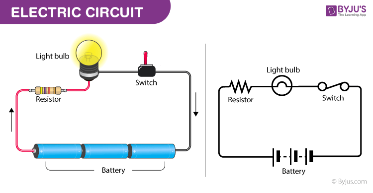
A typical circuit diagram of a DC circuit consists of a power source represented by a voltage symbol, conductors represented by wires, resistors represented by zigzag lines, and other components as required. The circuit diagram provides a visual representation of how the components are connected in the circuit and the flow of electrical current.
2. Alternating Current (AC) Circuit
2.1 Definition and Characteristics
An Alternating Current (AC) Circuit is a type of electrical circuit in which the direction of the electric current periodically changes. The current alternates between positive and negative cycles, continuously reversing its direction. AC circuits are commonly used in household electrical systems and power grids. The main advantage of AC circuits is the ability to transmit electricity over long distances more efficiently than DC circuits.
2.2 Components of an AC Circuit
Similar to a DC circuit, an AC circuit also consists of a power source, conductors, and various components such as resistors, capacitors, and inductors. However, AC circuits require additional components, such as transformers and generators, to facilitate the generation and conversion of alternating current.
2.3 Circuit Diagram of an AC Circuit
The circuit diagram of an AC circuit is similar to that of a DC circuit, but with the addition of components specific to AC circuits. The power source in an AC circuit is represented by a sinusoidal waveform, indicating the alternating nature of the current. The other components are represented in the same way as in a DC circuit diagram.
3. Series Circuit
3.1 Definition and Characteristics
A Series Circuit is a type of electrical circuit in which the components are connected one after another in a single path. In a series circuit, the same current flows through each component, and the voltage across each component adds up to the total voltage of the circuit. If one component fails in a series circuit, the entire circuit is affected, and the flow of current stops.
3.2 Components of a Series Circuit
A series circuit consists of a power source, conductors, and multiple components connected in series. Each component, such as resistors, capacitors, or inductors, is connected end to end, forming a single path for the flow of current.
3.3 Circuit Diagram of a Series Circuit
The circuit diagram of a series circuit illustrates the components connected in series, with the power source at one end and the return path at the other end. The components are connected in succession, with arrows indicating the direction of the current flow.
4. Parallel Circuit
4.1 Definition and Characteristics
A Parallel Circuit is a type of electrical circuit in which the components are connected in parallel branches, providing multiple paths for the flow of current. In a parallel circuit, the voltage across each component remains the same, while the current divides among the branches. This allows for the independent operation of each component, and if one component fails, the others continue to function.
4.2 Components of a Parallel Circuit
A parallel circuit includes a power source, conductors, and multiple components connected in parallel. Each component has its own branch, connecting one end to the positive terminal and the other end to the negative terminal of the power source.
4.3 Circuit Diagram of a Parallel Circuit
The circuit diagram of a parallel circuit depicts the power source connected to multiple components arranged in parallel branches. The branches join at a common node, connecting to the return path of the circuit. Arrows indicate the direction of the current flow within each branch.
5. Combination Circuit
5.1 Definition and Characteristics
A Combination Circuit is a type of electrical circuit that combines elements of both series and parallel circuits. This allows for a more complex arrangement of components to meet specific requirements. Combination circuits are commonly used in real-world applications where a combination of series and parallel connections is necessary.
5.2 Components of a Combination Circuit
A combination circuit includes a mix of series and parallel connections, involving a power source, conductors, and various components connected in different configurations. The combination of elements provides unique advantages for specific applications.
5.3 Circuit Diagram of a Combination Circuit
The circuit diagram of a combination circuit represents the various components connected in a combination of series and parallel configurations. It portrays the complexity of the circuit by illustrating the different paths for the flow of current and the arrangement of components.
6. Basic Components of Electric Circuits
6.1 Power Source
The power source is the component that provides the electrical energy to the circuit. It can be a battery, generator, or any other device capable of producing a steady supply of voltage.
6.2 Conductors
Conductors are materials or wires that enable the flow of electric current. They are typically made of metals with high electrical conductivity, such as copper or aluminum.
6.3 Insulators
Insulators are materials that restrict the flow of electric current. They prevent the electricity from leaking or dissipating, ensuring the current flows through the desired path.
6.4 Resistor
A resistor is a passive component that limits the flow of current in a circuit. It is commonly used to control or regulate the amount of current flowing through a circuit.
6.5 Capacitor
A capacitor is an electronic component that stores electrical energy in the form of an electric field. It consists of two conductive plates separated by an insulating material, known as a dielectric.
6.6 Inductor
An inductor is a coil of wire that stores electrical energy in the form of a magnetic field. It resists changes in current flow and can store energy in magnetic fields.
7. Key Terms
7.1 Voltage
Voltage is a measure of the electric potential difference between two points in a circuit. It determines the force with which the electric charges flow through the circuit.
7.2 Current
Current is the flow of electric charges in a circuit. It represents the rate at which electric charges move past a point in a conductor.
7.3 Resistance
Resistance is a measure of the opposition encountered by an electric current as it flows through a component or material. It determines the amount of current that can flow through a circuit.
7.4 Ohm’s Law
Ohm’s Law states that the current flowing through a conductor is directly proportional to the voltage applied across it and inversely proportional to its resistance. It is represented by the formula I = V/R, where I is the current, V is the voltage, and R is the resistance.
7.5 Power
Power is the rate at which electrical energy is consumed or produced in a circuit. It is calculated by multiplying the voltage across a component by the current flowing through it.
7.6 Frequency
Frequency refers to the number of complete cycles or oscillations of an AC waveform that occur in one second. It is measured in Hertz (Hz).
8. Importance and Applications of Understanding Electric Circuits
Understanding electric circuits is of utmost importance in various applications. It forms the foundation of electrical engineering and provides the knowledge necessary for designing, analyzing, and troubleshooting electrical systems. Knowledge of electric circuits is essential in the fields of power generation, distribution, communication systems, electronics, and much more. It enables engineers and technicians to effectively work with electrical systems, ensuring safety, efficiency, and reliable operation.
9. Conclusion
In conclusion, electric circuits play a vital role in our modern world. By understanding the five main electric circuits – Direct Current (DC) circuit, Alternating Current (AC) circuit, Series circuit, Parallel circuit, and Combination circuit – along with the basic components and key terms associated with them, we gain a comprehensive understanding of how electricity behaves and flows. This knowledge is crucial for various applications, ranging from battery-operated devices to power grids. Whether you are an electrical engineer, a student, or simply interested in knowing more about electricity, understanding electric circuits is a valuable skill that allows us to harness the power of electricity and utilize it in countless ways.